How to Coordinate Upstream and Downstream MCCBs: A Guide to Selective Protection
By Jimmy Zheng | International Business Manager at SSPD
Quick Answer: How Do You Coordinate Upstream and Downstream MCCBs?
To coordinate upstream and downstream molded case circuit breakers (MCCBs), engineers must evaluate load conditions, prospective short-circuit current, trip settings, time-current characteristic curves, and manufacturer selectivity data. The objective is to ensure that the circuit breaker closest to a fault interrupts the affected circuit while upstream protection remains closed, within the verified selectivity range.
Why Is MCCB Coordination Important?
In an industrial electrical distribution system, a short circuit in one branch should not unnecessarily interrupt power to the entire facility.
When upstream and downstream MCCBs are not properly coordinated, both breakers may trip during a downstream fault. This can disconnect healthy circuits, interrupt production, and make fault diagnosis more difficult.
For example, a fault in a small auxiliary distribution panel may cause the main distribution breaker to trip if the protective devices are not adequately coordinated.
Selective coordination helps limit the interruption to the affected part of the electrical system. However, it must be verified for the actual devices, settings, and available fault-current conditions rather than assumed from their current ratings.
What Is Selectivity Between Circuit Breakers?
Selectivity, also called discrimination, is the ability of a protective system to isolate a fault using the protective device closest to the fault, while upstream devices remain operational.
In a typical distribution system, the upstream MCCB protects a main feeder or distribution board, while a downstream MCCB protects a branch circuit or individual load.
When a fault occurs downstream, the desired response is for the downstream MCCB to interrupt the fault without unnecessarily disconnecting the upstream supply.
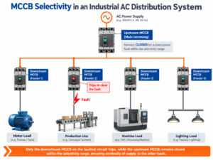
There are three important outcomes:
- Total selectivity: Selectivity is maintained throughout the specified fault-current range, up to the applicable limit defined by the manufacturer’s coordination data.
- Partial selectivity: Selectivity is maintained only up to a specified fault-current limit.
- No verified selectivity: The available evidence does not establish that the downstream MCCB will trip without the upstream device also operating under the conditions being evaluated.
The distinction between total and partial selectivity is important. A breaker combination may coordinate successfully for overloads and lower fault currents but lose selectivity when the short-circuit current becomes sufficiently high.
For additional technical background, consult the Electrical Installation Guide’s explanation of circuit-breaker coordination.
How to Coordinate Upstream and Downstream MCCBs
A reliable coordination study follows a systematic process. Selecting a larger upstream breaker and a smaller downstream breaker is not enough.
Step 1: Define the Electrical System
Start by identifying the distribution arrangement and the operating conditions.
Collect the following information:
- System voltage and frequency
- Single-line diagram
- Transformer or other power-source characteristics
- Upstream and downstream MCCB models
- Rated currents and breaking capacities
- Trip-unit types and protection settings
- Cable sizes and relevant load characteristics
- Maximum prospective short-circuit current at each relevant location
The power source matters because the available fault current may change with transformer configuration, generator operation, or alternative supply arrangements.
Where multiple operating configurations are possible, coordination should be evaluated for each relevant configuration.
Step 2: Determine the Prospective Short-Circuit Current
The prospective short-circuit current is the current that could flow at a particular point under a specified fault condition before the protective device limits or interrupts it.
This value is essential for evaluating whether a breaker can safely interrupt the fault and whether the upstream and downstream devices can coordinate.
Engineers should determine the available fault current at the relevant installation points using an appropriate short-circuit calculation or a verified system study.
A breaker with an insufficient breaking capacity must not be selected simply because its rated current is suitable for the load.
The upstream and downstream devices must each satisfy the applicable short-circuit protection requirements. If a tested cascading or backup-protection arrangement is proposed, its suitability must be confirmed using the manufacturer’s documented combination data.
Step 3: Check MCCB Ratings and Protection Functions
Review the relevant ratings and protection functions of both MCCBs.
| Parameter | What to check |
|---|---|
| Rated current | Suitability for the load and conductor protection requirements |
| Rated operational voltage | Compatibility with the electrical system |
| Icu | Ultimate short-circuit breaking capacity |
| Ics | Service short-circuit breaking capacity |
| Trip characteristics | Overload, short-circuit and other applicable protection functions |
| Adjustable settings | Actual long-time, short-time, instantaneous or ground-fault settings, where provided |
The exact parameters available depend on the MCCB model and trip-unit configuration.
A higher upstream current rating may help establish a protection hierarchy, but it does not prove selectivity. The actual tripping behavior of both devices must be evaluated.
Step 4: Compare Time-Current Characteristic Curves
A time-current characteristic (TCC) curve shows how a protective device’s operating time varies with current.
For coordination analysis, engineers compare the upstream and downstream curves over the relevant current range.
The graph typically uses current on the horizontal axis and operating time on the vertical axis, with logarithmic scales commonly used for both.
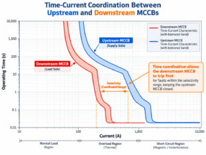
The comparison should consider:
- Overload operation
- Lower short-circuit currents
- Short-time protection, where available
- Instantaneous protection
- Relevant tolerance bands and operating characteristics
At lower fault-current levels, the upstream device’s operating time generally needs to remain sufficiently longer than the downstream device’s operating time to allow selective interruption.
However, curves alone may not establish selectivity under high short-circuit conditions. Current-limiting behavior and the interaction between the two breakers can affect the outcome.
Important: A conceptual TCC diagram explains the principle but cannot verify a particular SSPD breaker combination. Actual coordination decisions require the correct product curves, settings, and applicable manufacturer data.
Step 5: Verify the Manufacturer’s Selectivity Data
For high short-circuit currents, manufacturer selectivity tables or other validated coordination data are particularly important.
These documents may identify the maximum fault current up to which a specific upstream and downstream breaker combination maintains selectivity.
When reviewing a table, confirm that the following match the proposed installation:
- Exact upstream and downstream breaker ranges and models
- Trip-unit types
- Protection settings or stated default assumptions
- Rated operational voltage
- Applicable current and fault conditions
- Any restrictions or installation conditions specified by the manufacturer
Do not assume that a selectivity result for one product combination applies to another combination with a similar current rating.
If the required combination is not covered by available data, request clarification or engineering verification from the manufacturer. Until sufficient evidence is available, the combination should not be described as fully selective.
Step 6: Evaluate the Complete Fault-Current Range
A coordination study should not examine only one convenient current value.
Consider the relevant range of prospective fault currents, including conditions in which the downstream breaker may enter its instantaneous tripping region.
The final evaluation should establish whether selectivity is total, partial up to a stated limit, or not demonstrated for the required operating conditions.
Where ground-fault protection is installed, its settings and coordination should also be evaluated as applicable.
If the electrical system can operate with different sources or configurations, verify the required operating cases rather than relying on a single calculation.
Methods of Selective Coordination
Several methods may be used to coordinate protective devices. Their suitability depends on the breaker design, trip-unit functions, system requirements, and manufacturer data.
1. Current Selectivity
Current selectivity uses differences between the protective devices’ current thresholds.
The downstream device is generally configured to respond to lower fault-current thresholds than the upstream device, where the available protection functions allow this arrangement.
This method may be effective over a particular current range. Its performance must still be checked against the devices’ actual characteristics, especially at high fault currents.
2. Time Selectivity
Time selectivity uses coordinated operating delays.
The downstream device is intended to interrupt the fault first, while the upstream device provides a longer operating time for faults within the downstream protection zone.
This method depends on the available trip-unit functions and the upstream breaker’s ability to withstand the fault for the required delay.
Time delays must not be introduced without considering the system’s short-circuit withstand capability and applicable safety requirements.
3. Energy Selectivity
Energy selectivity relies on the current-limiting and energy-limiting behavior of compatible protective devices.
Its performance depends on the specific breaker designs and their interaction during fault interruption. It should not be assumed from rated-current ratios or generic TCC comparisons alone.
Manufacturer-specific coordination data is particularly important for this method.
4. Zone-Selective Interlocking
Zone-selective interlocking (ZSI) uses compatible protection equipment and signaling between protective devices to improve coordination.
For example, an upstream device may change its response when it receives a signal indicating a downstream fault.
ZSI is available only on compatible equipment and is not a universal feature of MCCBs. Its implementation requires the appropriate trip units, wiring, settings, and manufacturer instructions.
Worked Example: Evaluating Two MCCBs in an Industrial Distribution System
Consider an illustrative industrial distribution system with a main feeder protected by an upstream MCCB and a branch circuit protected by a downstream MCCB.
The branch circuit supplies equipment that may experience an overload or short circuit during operation.
The engineering objective is to isolate a branch-circuit fault without unnecessarily interrupting the main feeder.
A practical assessment would follow these steps:
First, establish the system conditions. Confirm the voltage, power-source configuration, breaker models, protection settings, and available short-circuit current at the branch circuit.
Second, check each device independently. Verify that the upstream and downstream MCCBs are suitable for their respective loads and meet the applicable short-circuit protection requirements.
Third, compare the protection characteristics. Review the actual time-current curves and determine whether the downstream device can operate first over the required current range.
Fourth, check the combination data. Confirm whether the exact pair of breakers has documented selectivity limits for the relevant voltage, settings, and fault conditions.
Finally, document the result. State the conditions under which selectivity is established and identify any limits or unresolved cases.
Without the relevant curves and manufacturer coordination data, this example cannot establish whether a particular MCCB combination is totally selective. It illustrates the verification process, not a tested product result.
Selectivity vs. Cascading: What Is the Difference?
Selectivity and cascading address different aspects of electrical protection.
Selectivity aims to ensure that the protective device closest to a fault interrupts the affected circuit while upstream devices remain closed, within the verified selectivity range.
Cascading, also called backup protection, uses the characteristics of an upstream protective device to help protect downstream equipment against short-circuit conditions that might otherwise exceed the downstream device’s standalone capability.
A cascading arrangement must be supported by appropriate manufacturer data for the specified combination. It should not be assumed to provide full selectivity.
These concepts are related but not interchangeable. A design may use cascading to meet short-circuit protection requirements without necessarily achieving the desired level of selective coordination.
For further technical guidance, refer to the Schneider Electric Selectivity, Cascading and Coordination Guide. Always verify that the information applies to the products being considered.
Common MCCB Coordination Mistakes
Mistake 1: Assuming a Higher Upstream Current Rating Guarantees Selectivity
Current ratings alone do not determine the complete tripping behavior of two breakers. Protection curves, trip settings, fault current, and device interaction must also be considered.
Mistake 2: Ignoring High Short-Circuit Currents
Two devices may coordinate over part of the operating range but lose selectivity at higher fault currents. The study must cover the relevant fault-current range.
Mistake 3: Treating TCC Curves as the Only Evidence
TCC curves are essential, but they may not fully establish coordination during high-current, current-limiting interruption. Manufacturer selectivity data may be required.
Mistake 4: Confusing Cascading With Selectivity
Backup protection does not automatically mean that the downstream breaker will interrupt every fault without the upstream breaker operating.
Mistake 5: Applying Data From the Wrong Breaker Combination
Coordination results may depend on the exact breaker model, trip unit, settings, voltage, and other stated conditions. Similar-looking products should not be treated as interchangeable without evidence.
MCCB Coordination Verification Checklist
Before finalizing a low-voltage distribution design, verify that:
- The single-line diagram and power-source configuration are confirmed.
- Prospective short-circuit currents have been established at relevant points.
- Both MCCBs have suitable ratings and protection functions.
- Actual trip settings and characteristic curves have been reviewed.
- The manufacturer’s selectivity data has been checked for the exact combination, where required.
- Partial selectivity limits, if applicable, have been documented.
- Cascading claims are supported by the relevant manufacturer data.
- Ground-fault protection and alternative operating configurations have been considered where applicable.
- Final settings and design decisions are reviewed by a qualified electrical professional.
Frequently Asked Questions
Does a higher-rated upstream MCCB guarantee selectivity?
No. A higher upstream current rating alone does not guarantee selectivity. The result depends on the breakers’ trip characteristics, settings, prospective fault current, and validated coordination data.
What is the difference between total and partial selectivity?
Total selectivity means coordination is maintained throughout the specified fault-current range up to the applicable limit. Partial selectivity means coordination is maintained only up to a defined fault-current value.
Can I coordinate MCCBs from different manufacturers?
It may be possible, but it must not be assumed. Confirm that the relevant curves and coordination data support the proposed combination. If validated information is unavailable, the coordination result remains unverified.
Do electronic trip MCCBs always provide better selectivity?
No. Electronic trip units may offer adjustable protection functions that help engineers develop a coordinated design, but the outcome depends on the actual device characteristics, settings, and system requirements.
Why might both upstream and downstream MCCBs trip during a short circuit?
Both breakers may respond to a high fault current if their operating characteristics overlap or if the combination does not maintain selectivity under that condition. The actual cause must be determined from the system study and device data.
Is cascading the same as selective coordination?
No. Cascading concerns backup short-circuit protection using a tested device combination. Selectivity concerns which protective device interrupts the fault. A cascading arrangement does not automatically establish total selectivity.
Conclusion
Coordinating upstream and downstream MCCBs requires more than selecting different current ratings. Engineers must evaluate system fault levels, protection settings, time-current characteristics, and manufacturer coordination data to establish the required level of selectivity.
A documented coordination study helps improve fault isolation, reduce unnecessary power interruptions, and support a more reliable low-voltage distribution system.
About SSPD
SSPD manufactures low-voltage electrical protection products, including molded case circuit breakers (MCCBs), air circuit breakers (ACBs), miniature circuit breakers (MCBs), motor protection circuit breakers (MPCBs), and AC contactors.
For project-related enquiries, buyers and switchgear manufacturers can contact SSPD with their system voltage, load requirements, proposed breaker models, and available fault-current information to discuss product suitability and the technical documentation needed for evaluation.
About the Author
Jimmy Zheng
International Business Manager at SSPD
Jimmy Zheng focuses on low-voltage electrical products and international B2B business, working with distributors, switchgear manufacturers, and industrial customers on product selection and sourcing requirements.
His areas of focus include MCCBs, ACBs, MCBs, MPCBs, AC contactors, and low-voltage circuit protection solutions.