How Does an MCCB Trip Unit Work?
By Jimmy Zheng · Reviewed by SSPD Engineering Team · Updated September 2026
Quick Answer
An MCCB trip unit monitors the current flowing through a circuit and initiates a trip when an overload or short circuit reaches its protection threshold. During a sustained overload, the trip is typically delayed, while a severe short circuit requires a much faster response. Thermal-magnetic trip units use thermal and electromagnetic elements, while electronic trip units use current sensing and electronic logic to provide more flexible protection characteristics.
When an MCCB trips, the operating handle is what users see. However, the trip unit is the part of the protection system that determines whether a fault condition requires the breaker to open.
This is also why a 250 A MCCB does not simply trip the instant current exceeds 250 A. Actual tripping behavior depends on the magnitude and duration of the current, the trip characteristic, protection settings, and the type of trip unit installed.
Understanding how these elements work together is important when selecting an MCCB for an industrial distribution system.
What Is an MCCB Trip Unit?
The trip unit is the sensing and decision-making part of an MCCB protection system. Its main purpose is to detect abnormal current conditions and initiate tripping when the defined protection conditions are reached.
It is useful to distinguish the trip unit from two other parts of the breaker.
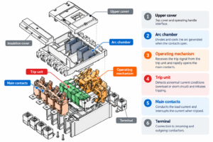
The trip unit detects and evaluates the overcurrent condition. The operating mechanism releases and opens the main contacts after a trip is initiated. The arc extinguishing system then controls and extinguishes the arc created when the contacts separate.
The basic protection sequence can therefore be understood as:
Current Detection → Protection Decision → Trip Mechanism → Contact Separation → Arc Interruption
This distinction matters because the trip unit does not simply “switch off” the current by itself. It determines when tripping is required and initiates the mechanical interruption process.
How Does an MCCB Trip Unit Work Step by Step?
Although the sensing technology varies between thermal-magnetic and electronic trip units, the overall protection process follows the same basic logic.
Step 1: Current Flows Through the MCCB
During normal operation, load current passes through the MCCB main circuit.
As long as the current remains within acceptable operating conditions, the breaker stays closed and supplies power to the downstream circuit.
The trip unit continuously responds to or monitors this current, depending on its design.
Step 2: The Trip Unit Detects the Current Condition
The method of current detection depends on the trip-unit technology.
A thermal-magnetic trip unit uses thermal and electromagnetic effects to respond to overcurrent conditions.
An electronic trip unit uses current sensing together with electronic processing to evaluate the current against its protection characteristics and settings.
Step 3: The Current Is Evaluated Against the Protection Characteristic
An MCCB does not treat every overcurrent condition in the same way.
A small temporary overload may not require immediate interruption. A sustained overload should eventually cause the breaker to trip. A severe short circuit, however, normally requires a much faster response.
The trip decision therefore depends on factors such as:
- Current magnitude
- Duration of the overcurrent
- Trip characteristic
- Protection settings
- Trip-unit design
This relationship between current and time is fundamental to understanding MCCB protection.
Step 4: The Trip Unit Initiates Tripping
When the applicable protection threshold and time condition are reached, the trip unit releases or commands the tripping mechanism.
The operating mechanism then rapidly separates the main contacts.
Step 5: The Main Contacts Open
As the contacts separate under load or fault current, an electrical arc forms between them.
Simply separating the contacts is therefore not enough to interrupt a high fault current safely.
Step 6: The Arc Is Extinguished
The MCCB directs the arc into its arc-extinguishing system, where the arc is divided, cooled, and extinguished.
Once the arc is extinguished, current flow through the faulted circuit is interrupted.
This completes the protection sequence:
Fault Current → Detection → Trip Decision → Mechanism Release → Contacts Open → Arc Extinction
How Does an MCCB Respond to Different Current Conditions?
One of the most important things to understand about an MCCB trip unit is that different fault conditions require different responses.
| Circuit Condition | Trip Unit Response | Typical Result |
|---|---|---|
| Normal load | Current remains within acceptable range | No trip |
| Temporary moderate overload | Overcurrent exists for a short period | Breaker may remain closed |
| Sustained overload | Overcurrent continues | Delayed trip |
| High short-circuit current | Very high fault current detected | Rapid or instantaneous trip |
| Ground fault | Detected where the trip unit provides GF protection | Trip according to applicable settings |
In general, overload protection uses a time-current relationship: the magnitude of the overcurrent and how long it persists both matter.
However, the statement that “higher current always means faster tripping” should not be treated as an absolute rule. Actual operation depends on the protection curve, pickup settings, intentional time delays, I²t characteristics, and the specific trip-unit design.
How Does a Thermal-Magnetic MCCB Trip Unit Work?
A thermal-magnetic trip unit combines two different physical protection principles.
Thermal Protection for Overloads
The thermal element is primarily used for overload protection.
When current above the intended operating level continues to flow, heat builds up in the thermal element. A bimetallic element responds to this temperature increase by bending.
If the overload persists sufficiently, the movement of the bimetal eventually causes the breaker mechanism to trip.
This thermal behavior provides an intentional time delay.
That delay is useful because many electrical loads can experience temporary current increases without an actual fault. Tripping immediately for every brief overload could result in unnecessary interruptions.
Magnetic Protection for Short Circuits
Short circuits require a much faster response.
When a very high fault current flows through the magnetic trip element, it produces a strong magnetic force. This force operates an armature or similar mechanism and releases the breaker rapidly.
The two functions therefore complement each other:
Thermal protection → sustained overload
Magnetic protection → high short-circuit current
This is the basic reason these devices are called thermal-magnetic trip units.
How Does an Electronic MCCB Trip Unit Work?
Electronic trip units perform the same fundamental protection task but use current sensing and electronic processing rather than relying only on thermal and magnetic elements.
A simplified operating sequence is:
Current Sensing → Signal Processing → Protection Logic → Trip Command → Operating Mechanism
Depending on the MCCB and trip-unit model, electronic protection can provide functions such as:
- Long-time overload protection
- Short-time short-circuit protection
- Instantaneous protection
- Ground-fault protection
- Adjustable pickup levels
- Adjustable time delays
The main advantage is not simply that an electronic trip unit is “more advanced.” Its value is the greater flexibility it can provide when protection settings and coordination need to be carefully controlled.
For example, an industrial main distribution system may require coordination between several upstream and downstream circuit breakers. Adjustable electronic protection can make this easier to achieve than a basic fixed protection arrangement.
However, electronic protection is not automatically the best choice for every application. A simpler thermal-magnetic MCCB may provide all the protection required for many general distribution circuits.
Thermal-Magnetic vs Electronic MCCB Trip Units
| Feature | Thermal-Magnetic Trip Unit | Electronic Trip Unit |
|---|---|---|
| Detection principle | Thermal and electromagnetic effects | Current sensing and electronic processing |
| Overload protection | Yes | Yes |
| Short-circuit protection | Yes | Yes |
| Adjustment flexibility | Basic or model-dependent | Generally wider |
| Protection coordination | Basic | More flexible |
| Ground-fault protection | Model-dependent | Available on selected units |
| Complexity | Lower | Higher |
| Typical use | General distribution | More demanding industrial distribution |
The correct choice depends on the application rather than simply choosing the trip unit with the greatest number of functions.
What Do Common MCCB Trip Settings Such as Ir, Isd and Ii Mean?
Electronic MCCBs—and some adjustable protection systems—may show several protection settings on the trip unit.
Three common terms are Ir, Isd and Ii.
Ir — Long-Time or Overload Pickup
Ir defines the pickup level associated with long-time overload protection.
It is closely related to the continuous current that the protected circuit is intended to carry.
Isd — Short-Time Pickup
Isd is commonly associated with short-time short-circuit protection.
This function can allow the breaker to tolerate certain fault-current levels for a controlled period before tripping, which can be useful for protection coordination.
Ii — Instantaneous Pickup
Ii is the pickup level for instantaneous protection.
When current reaches the applicable instantaneous protection threshold, the breaker responds without an intentional time delay associated with short-time protection.
Other settings may include:
- tr — long-time delay
- tsd — short-time delay
- Ig — ground-fault pickup
- tg — ground-fault delay
These terms should not be treated as universal features of every MCCB.
The available functions, terminology, adjustment ranges, and fixed or adjustable characteristics vary between manufacturers and trip-unit models. Always check the technical documentation for the specific breaker being selected.
MCCB Frame Rating, Trip Unit Rating and Trip Setting Are Not the Same Thing
This is one of the most common areas of confusion when selecting an MCCB.
Suppose an MCCB is marked as a 250 A frame.
That does not automatically mean:
Current reaches 251 A → MCCB trips immediately.
Several different concepts may be involved:
Frame Rating → Trip-Unit Rating/Range → Protection Setting → Actual Trip Characteristic
For example, consider an illustrative electronic MCCB configuration where the applicable overload pickup is set to:
Ir = 0.8 × 250 A = 200 A
Even then, this does not mean the breaker will necessarily trip the instant current reaches 201 A.
The actual trip time depends on the applicable time-current characteristic and how long the overcurrent persists.
This distinction is especially important when engineers are coordinating the MCCB with cable capacity, load characteristics, and downstream protective devices.
Common MCCB Trip Unit Mistakes
1. Confusing Rated Current With the Actual Trip Point
The current marked on an MCCB should not automatically be interpreted as the exact current at which it will instantly trip.
Always consider the trip characteristic and protection settings.
2. Setting the Overload Pickup Too Low
A very low setting does not necessarily mean better protection.
If the protection setting does not match the normal operating characteristics of the load, nuisance tripping may occur.
3. Setting Protection Too High
The opposite can also create problems.
Protection settings must still adequately protect cables and downstream equipment against abnormal current conditions.
4. Ignoring Coordination With Other Circuit Breakers
In a distribution system, the MCCB usually does not operate alone.
If upstream and downstream protective devices are poorly coordinated, a downstream fault may interrupt a much larger section of the electrical system than necessary.
This is why selectivity and protection coordination should be considered when setting adjustable trip units.
5. Assuming an Electronic Trip Unit Is Always Better
Electronic trip units provide useful flexibility, but additional functions only create value when the application requires them.
For a straightforward distribution feeder, a correctly selected thermal-magnetic MCCB may be entirely appropriate.
How Do You Choose the Right MCCB Trip Unit?
Start with the application rather than the trip-unit technology.
Consider five questions:
- What type of load is being protected?
Motor loads, general distribution, transformers, and other applications can have different operating characteristics. - What overload and short-circuit protection is required?
Protection must match both the load and the electrical system. - Do you need adjustable protection settings?
More complex systems may benefit from adjustable pickup levels and delays. - Is coordination with other breakers important?
Main and sub-distribution systems often require more careful coordination. - Are additional protection functions required?
Functions such as ground-fault protection are available only on applicable trip units.
The right trip unit is therefore not necessarily the one with the most functions. It is the one that provides the required protection and coordination for the application.
For broader MCCB selection, also consider rated current, system voltage and breaking capacity. See our guides on How to Select the Right MCCB for Industrial Applications, What Size MCCB Do I Need?, How to Choose MCCB Breaking Capacity, and Icu vs Ics in MCCB.
Frequently Asked Questions
What causes an MCCB trip unit to operate?
An MCCB trip unit operates when the electrical conditions meet its defined protection characteristic or settings. Depending on the trip unit, this may include sustained overload, short circuit, and certain additional faults such as ground faults.
What is the difference between a trip unit and an MCCB operating mechanism?
The trip unit detects or evaluates the fault condition and initiates tripping. The operating mechanism physically releases and opens the breaker contacts.
What is the difference between thermal-magnetic and electronic trip units?
Thermal-magnetic trip units use thermal and electromagnetic effects to provide overload and short-circuit protection. Electronic trip units use current sensing and electronic processing and generally provide greater flexibility in protection settings.
Can an MCCB trip unit be adjusted?
Some can, while others have fixed or partially adjustable characteristics. The available adjustment depends on the MCCB and specific trip-unit model.
What do Ir, Isd and Ii mean?
Ir commonly refers to long-time overload pickup, Isd to short-time pickup, and Ii to instantaneous pickup. Exact terminology and available adjustments should always be confirmed from the manufacturer’s technical documentation.
Why does an MCCB sometimes trip immediately?
A very high short-circuit current may reach the instantaneous protection threshold, causing the MCCB to trip rapidly. Other possible causes depend on the breaker configuration and electrical system, so the actual trip condition should be investigated before resetting the breaker.
About SSPD
SSPD manufactures low-voltage circuit protection products for industrial power distribution applications, including MCCBs with different frame sizes and protection configurations.
When selecting an MCCB, customers can provide the system voltage, load current, required breaking capacity, application and protection requirements so that the appropriate configuration can be evaluated.
Need help selecting an MCCB or trip unit for your application? Contact SSPD with your electrical system requirements for selection support.
About the Author
Jimmy Zheng
International Business Manager at SSPD
Jimmy Zheng has more than 10 years of experience in low-voltage electrical products and international B2B business, working with electrical distributors, switchgear manufacturers and industrial customers on circuit protection and motor-control product selection.
Technical Review: SSPD Engineering Team
Reviewed for technical accuracy, product specifications and applicable low-voltage circuit protection principles.