An MCCB trip curve helps engineers understand how a molded case circuit breaker responds to different levels of overcurrent. However, reading the curve incorrectly can lead to unsuitable protection settings, unwanted tripping, or coordination problems between circuit breakers.
In this guide, we explain how to read the current and time axes, understand thermal-magnetic and electronic trip characteristics, interpret a trip band, and use time-current curves to evaluate protection coordination.
Quick Answer: What Does an MCCB Trip Curve Show?
An MCCB trip curve, also called a time-current characteristic curve, shows the relationship between the current flowing through a circuit breaker and its operating or clearing time under specified conditions. Engineers use it to estimate response times at different current levels, understand overload and short-circuit protection behavior, and assess coordination between protective devices. The actual response depends on the breaker model, trip unit, settings, and operating conditions.
1. What Is an MCCB Trip Curve?
An MCCB trip curve is a technical graph that describes how a molded case circuit breaker responds to different overcurrent levels.
It helps engineers answer three practical questions:
- At a particular current, how long might the breaker take to operate?
- How does its response change as the current increases?
- Will its protection characteristics work appropriately with the connected load and other protective devices?
The curve is particularly useful when evaluating overload protection, short-circuit protection, and coordination between upstream and downstream circuit breakers.
However, not every MCCB has the same trip characteristics. Thermal-magnetic breakers and electronic-trip breakers can have different response profiles and adjustment options.
Always use the curve applicable to the specific breaker and trip unit being evaluated.
2. How to Read the Axes of an MCCB Trip Curve
Before interpreting the curve, identify what each axis represents.
X-Axis: Current
The horizontal axis represents current. Depending on the manufacturer’s documentation, it may use:
- Actual current in amperes (A).
- Multiples of the rated current, such as (2 \times I_n).
- Multiples of an adjustable trip setting, such as (2 \times I_r).
These references are not interchangeable.
For example, if the rated current is 100 A and the curve uses rated current as its reference, 200 A corresponds to (2 \times I_n). If the curve instead uses an adjustable long-time pickup setting, the calculation must use that setting.
Always read the axis label and curve legend before calculating the current multiple.
Y-Axis: Time
The vertical axis represents time, commonly in seconds.
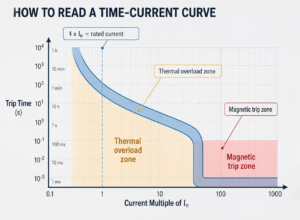
Many MCCB time-current curves use logarithmic scales on both axes. This means that equal spacing can represent multiplication rather than equal numerical increments.
Do not interpret a logarithmic axis as a linear scale.
Also check whether the manufacturer presents operating time, tripping time, or total clearing time. These terms may describe different stages of the protective operation.
3. Understanding the Main Regions of an MCCB Trip Curve
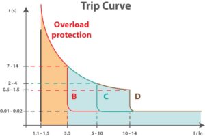
The curve’s shape depends on the protection technology and the specific trip unit. Thermal-magnetic MCCBs typically illustrate inverse-time overload behavior and a magnetic high-current trip region. Electronic-trip MCCBs may show several distinct protection functions and adjustable delays.
Thermal Overload Region
In a thermal-magnetic MCCB, overload protection commonly uses a thermal element, such as a bimetallic mechanism.
Under sustained overload conditions, heating causes the element to respond and initiate tripping.
This produces an inverse-time characteristic over the relevant operating range: generally, a larger overload results in a shorter operating time.
For example, a moderate overload may be tolerated for a longer period than a much larger overload. The actual response must be determined from the applicable product curve.
Ambient temperature, the breaker’s previous thermal state, and the manufacturer’s stated test conditions may also affect the result.
Magnetic Instantaneous Trip Region
Magnetic protection responds to high current through an electromagnetic mechanism.
When current reaches the applicable magnetic trip threshold, the mechanism initiates rapid tripping, without an intentionally introduced time delay in the instantaneous function.
However, instantaneous does not mean zero time. Mechanical operation and interruption of the current still take time.
The pickup threshold and actual response depend on the breaker design and, where applicable, its adjustment settings. Do not assume that every MCCB uses the same instantaneous trip multiple.
Understanding the Trip Band
A manufacturer’s time-current curve may show a band rather than one exact line.
The boundaries may represent specified minimum and maximum operating or clearing times, depending on the manufacturer’s definitions and test conditions.
To interpret the band correctly:
- Read the curve legend.
- Identify what the upper and lower boundaries represent.
- Check the applicable trip settings and operating conditions.
- Use the specified range rather than assuming a single exact trip time.
4. How to Read an MCCB Trip Curve Step by Step
Use the following procedure when reviewing a manufacturer’s time-current curve.
Step 1: Identify the MCCB Model and Trip Unit
Confirm the exact product family, current rating, trip unit type, and relevant settings.
A curve for one breaker model should not automatically be applied to another model with the same rated current.
Step 2: Identify the Current Reference
Check whether the horizontal axis uses amperes, rated current, or an adjustable pickup setting.
If the axis uses a current multiple, calculate the multiple using the reference specified on the curve.
Step 3: Locate the Current of Interest
Find the current you want to evaluate on the horizontal axis.
For example, this might be a sustained overload current or an estimated fault current obtained from an electrical system study.
Step 4: Follow the Curve
Move vertically from the selected current until you reach the relevant curve boundary or region.
If the curve shows a band, note the corresponding range rather than selecting an arbitrary point.
Step 5: Read the Time Range
Move horizontally toward the vertical axis to identify the corresponding time values.
Confirm whether these values represent trip time or total clearing time, as specified by the manufacturer.
Step 6: Check the Application
Compare the result with the circuit’s protection requirements, conductor characteristics, load behavior, and coordination requirements.
A curve reading is only one part of a complete protection assessment.
5. Worked Example: Reading a Trip Curve
Consider a hypothetical MCCB with a rated current of 100 A.
An engineer wants to understand how to locate an operating current of 200 A on a curve whose horizontal axis explicitly uses multiples of rated current, (I_n).
The current multiple is:
[
\frac{200\text{ A}}{100\text{ A}}=2
]
Therefore, the evaluation point is (2 \times I_n).
The engineer can then locate this current multiple on the horizontal axis, move vertically to the applicable curve region, and read the corresponding time range.
The important distinction is that the calculation identifies the position on the horizontal axis. It does not determine the trip time by itself.
The actual time must be read from the relevant manufacturer’s curve for the specific MCCB and its applicable conditions.
This example demonstrates the reading method only. It does not represent measured SSPD product performance or establish a recommended protection setting.
6. Thermal-Magnetic vs. Electronic MCCB Trip Curves
Thermal-magnetic and electronic-trip MCCBs can both be evaluated using time-current characteristics, but their protection mechanisms and adjustment options differ.
Thermal-Magnetic MCCB
A thermal-magnetic trip unit commonly combines:
- Thermal overload protection.
- Magnetic short-circuit protection.
Depending on the model, some settings may be fixed while others may be adjustable.
Its curve typically shows inverse-time overload behavior and a high-current magnetic trip region.
Electronic-Trip MCCB
An electronic trip unit measures current and processes it through electronic protection circuitry.
Depending on the specific trip unit, the available functions may include:
- Long-time protection.
- Short-time protection.
- Instantaneous protection.
- Ground-fault protection, where provided.
Electronic-trip curves may contain several sections, reflecting pickup thresholds and intentional time delays.
For these breakers, the engineer must check the actual settings and the meaning of each curve segment. Not every electronic-trip MCCB provides all the functions listed above.
The main lesson is simple: never interpret an electronic-trip curve as if it were automatically identical to a basic thermal-magnetic curve.
7. How Are MCCB Trip Curves Used in Protection Coordination?
Protection coordination aims to ensure that protective devices respond appropriately to faults while limiting unnecessary interruption of healthy parts of the electrical system.
For example, if a fault occurs on a downstream branch circuit, the design may aim for the downstream breaker to clear the fault without unnecessarily tripping the upstream breaker.
Engineers can compare the time-current characteristics of upstream and downstream devices to evaluate their operating relationships across different current levels.
However, visual comparison alone does not prove selectivity.
Actual coordination can depend on:
- The specific breaker models and trip units.
- Pickup and time-delay settings.
- The prospective short-circuit current.
- Total clearing characteristics.
- Manufacturer-tested coordination data for the relevant device combination.
Where the project requires selective coordination, consult the applicable manufacturer coordination tables and engineering data rather than relying solely on a generic trip curve.
8. Common Mistakes When Reading MCCB Trip Curves
Several errors can lead to incorrect conclusions.
Mistake 1: Treating logarithmic axes as linear.
Read the scale markings carefully before estimating current or time.
Mistake 2: Assuming the curve gives one exact trip time.
If the manufacturer specifies a range, use the range and its stated conditions.
Mistake 3: Ignoring the current reference.
A multiple of (I_n) is not necessarily the same as a multiple of (I_r).
Mistake 4: Ignoring trip settings.
Adjustable electronic or magnetic settings can change the applicable characteristic.
Mistake 5: Confusing trip time with total clearing time.
The time required to initiate tripping may differ from the time required to interrupt the current completely.
Mistake 6: Confusing trip characteristics with breaking capacity.
A time-current curve does not replace verification of the breaker’s rated short-circuit breaking capacity, such as Icu and Ics where applicable.
9. When Do You Need the Manufacturer’s Actual Trip Curve?
A generic diagram is useful for learning how to read a curve, but it is not sufficient for actual equipment selection or protection design.
For an engineering application, obtain the documentation applicable to the exact MCCB model and trip unit. Check the rated current, pickup settings, time delays, operating conditions, and the manufacturer’s definition of the displayed curve boundaries.
If coordination is required, also obtain the relevant coordination data for the proposed upstream and downstream devices.
For additional information on the scope of low-voltage circuit-breaker requirements, refer to the IEC 60947-2 standard overview.
Frequently Asked Questions
What does an MCCB trip curve show?
An MCCB trip curve shows the relationship between current and the corresponding tripping or clearing time under specified conditions. It helps engineers evaluate overload response, high-current protection, and coordination.
What do the X-axis and Y-axis represent?
The X-axis represents current, either in amperes or using a stated current reference. The Y-axis represents time, commonly in seconds. The scale and reference values must be checked on the actual curve.
Why is an MCCB trip curve shown as a band?
A curve band can show a range of operating or clearing times under specified conditions. Its exact meaning depends on the manufacturer’s legend and documentation.
What is the difference between thermal and magnetic tripping?
Thermal tripping generally provides inverse-time overload protection, while magnetic tripping responds rapidly to high current. Their exact characteristics depend on the breaker design.
Can an MCCB trip curve be used for protection coordination?
Yes. Curves help engineers compare the operating characteristics of protective devices. However, confirming selectivity may require manufacturer coordination tables, fault-current calculations, and verification of the actual device combination.
Does a higher breaking capacity mean a faster trip?
No. Breaking capacity and trip characteristics describe different properties. Breaking capacity concerns the fault current the breaker is rated to interrupt under specified conditions; the trip curve describes its current-time response.
Conclusion
Reading an MCCB trip curve requires identifying the current reference, understanding the time scale, recognizing the relevant trip region, and checking the manufacturer’s stated conditions. Thermal-magnetic and electronic-trip breakers may have different characteristics, so actual selection and coordination must be based on the specific product documentation.
Need Help Selecting an MCCB?
If you are evaluating MCCBs for an industrial distribution panel or switchgear project, provide the required current rating, system conditions, and protection requirements. The SSPD team can help you identify the relevant product information and documentation available for your application.
About SSPD
SSPD manufactures low-voltage electrical products, including molded case circuit breakers, air circuit breakers, miniature circuit breakers, motor protection circuit breakers, and AC contactors.
SSPD supports international B2B customers with product selection, manufacturing, and OEM/ODM requirements.
About the Author
Jimmy Zheng
International Business Manager at SSPD
Jimmy focuses on low-voltage electrical products and international B2B business, working with distributors, switchgear manufacturers, and project buyers on product selection and sourcing requirements.
Technical review: Add the name or designation of the responsible SSPD engineering reviewer after the technical review has been completed.