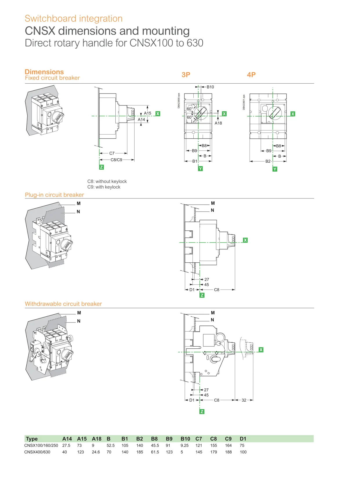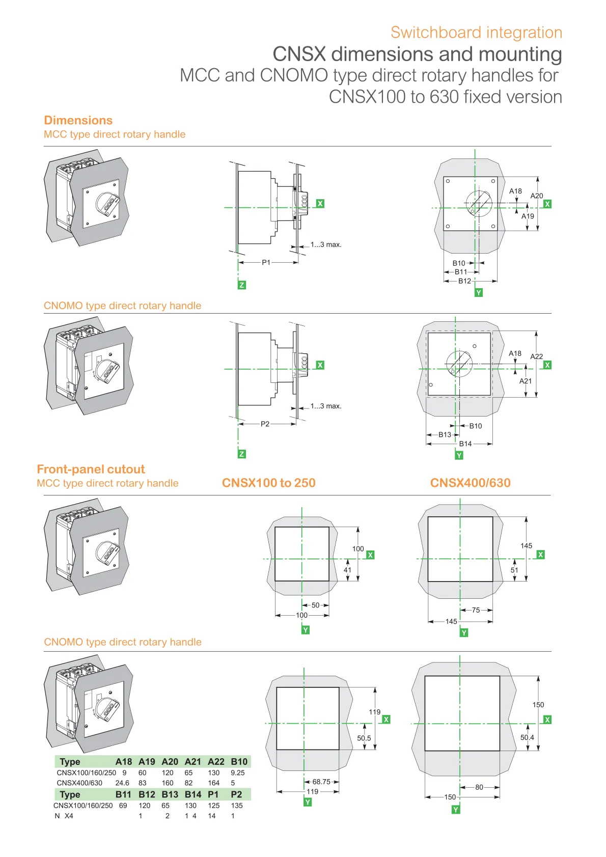
Direct rotary handles
Installation
The direct mounted rotary handle has to be mounted by 3 screws on the front accessory cover.
Operation
The direct rotary handle maintains:
- suitability for isolation
- indication of the three positions OFF (O), ON (I) and tripped (Trip)
- access to the “push-to-trip” button
- visibility and access to the trip unit.
Device padlocking
The circuit breaker may be locked in the OFF position by using one to three padlocks (not supplied) or in ON position after customer modification of the rotary handle before installation, padlock shackle Ø4-8 mm. Locking in the ON position does not prevent the circuit breaker from tripping if a fault occurs. In this case, the handle remains in the ON position after the circuit breaker trips. Unlocking is required for the handle to go to the tripped then the OFF position.
Variations: door locking
Door locking built-in functionality can be activated by the customer to prevent opening the door when the circuit breaker is ON or in trip position. For exceptional situations, door locking can be temporarily disabled with a tool by qualified personel to open the door when the circuit breaker is closed.
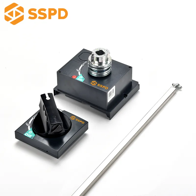
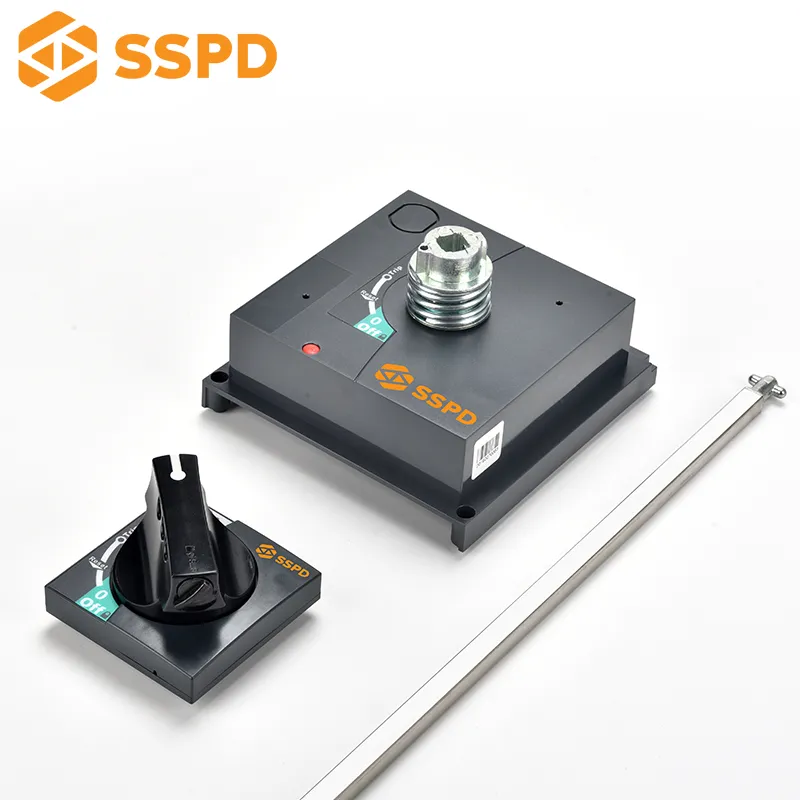
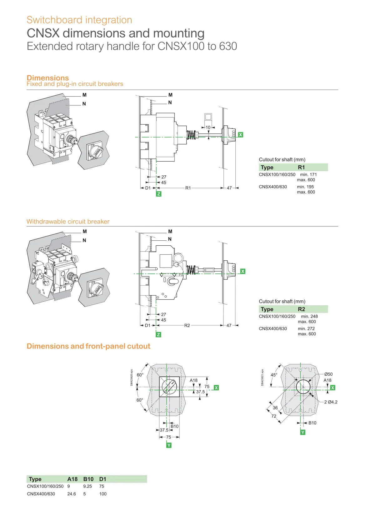
Extended rotary handles
Installation
The door-mounted (extended) rotary handle is made up of:
- a unit that has to be screwed on the front accessory cover of the circuit breaker
- an assembly (handle mechanism and front plate) on the door that is always secured in the same position, whether the circuit breaker is installed vertically or horizontally
- an adjustable extension shaft.
The handle mechanism is fixed with a nut (Ø22 mm) to make assembly easier. The Laser Square tool (GVAPL01) can be used to accurately align the hole on the door with the circuit breaker.
Operation when door is closed
The door mounted handle makes it possible to operate a circuit breaker installed in
an enclosure from the front. The door mounted operating handle maintains:
- suitability for isolation
- indication of the three positions OFF (O), ON (I) and tripped (Trip)
- visibility and access to trip unit when the door is open
- degree of protection of the handle on the door: IP54 or IP65 as per 60520.
Mechanical door locking when device closed
A standard feature of the extended rotary handle is a locking function, built into the shaft, that disables door opening when the circuit breaker is in the ON or tripped positions.
Door locking can be temporarily disabled with a tool by qualified personnel to open the door without opening the circuit breaker. This operation is not possible if the handle is locked by a padlock.
Device and door padlocking
Padlocking locks the circuit breaker handle and disables door opening:
●standard situation, in the OFF position, using 1 to 3 padlocks, shackle Ø4-8 mm,
padlocks are not supplied
●for the black handle, with a voluntary modification of the door handle (to be done
by the customer during installation), in the ON and OFF positions. Locking in the ON
position does not prevent the circuit breaker from tripping if a fault occurs. In this
case, the handle remains in the ON position after the circuit breaker trips. Unlocking
is required for the handle to go to the tripped then the OFF position.
Operation when door is opened
An open door shaft operator can be used to operate the circuit breaker when door is opened. This accessory complies with UL 508A.
The indication of the three positions OFF (O), ON (I) and tripped (Trip) is visible on the circuit breaker.
The circuit breaker itself may be locked in OFF position when the door is opened by 1 padlock / lockout hasp, shackle Ø4-8 mm.
Shaft length
The shaft length is the distance between the back of the circuit breaker and the door:
- minimum shaft length is 200 mm
- maximum shaft length is 600 mm
- shaft length must be adjusted.